
Last Update: 08/2018
IOS-XR EVPN – Distributed Anycast IRB Gateway, L2/L3VPN Service with MPLS Data Plane
Table of Content:
3. Services EVPN – IRB L2/l3VPN Multipoint
The previous document: “IOS-XR EVPN – Multipoint L2VPN Service with MPLS Data Plane” described configuration of EVPN – L2VPN multipoint service with MPLS data plane.
This document will briefly describe how to configure EVPN Distributed Anycast IRB Gateway for L2/L3VPN service. EVPN Distributed Anycast IRB Gateway provides transparent Layer3 Multi-Homing without additional protocols such as ICCP, vPC, VSS, nV Edge Cluster, etc. BGP EVPN is used as a common Control Plane for MAC, Host IP Address and IP prefixes distribution, as well as for Layer2/Layer3 information synchronization, such as MAC address table, ARP and IGMP.
With this approach, we get optimal Layer3 forwarding together with simplified Multi-Homed ethernet access configuration.
Diagram: “lab topology” displays lab topology, which emulates small Service Provider Data Center.
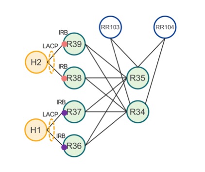
lab topology
Devices in the lab:
· Two Spines: R34 and R35 – Cisco NCS 5501-SE
· Four Leaves: R36, R37, R38 and R39 – Cisco NCS 5501-SE
· Two Router Reflectors: RR103 and RR104 – Cisco IOS XRv 9000
· Two Hosts: H1 and H2, both hosts are dual-homed
o H1 to R36 and R37
o H2 to R38 and R39
All interfaces are 10Gbps Ethernet connected by direct fiber.
All devices run Cisco IOS-XR 6.5.1 operating system.
Please note that transport configuration stays completely the same as in the previous document: “IOS-XR EVPN – Multipoint L2VPN Service with MPLS Data Plane”.
All devices except H1 and H2 are in the same IGP domain. H1 and H2 are connected to transparent EVPN – L2VPN multipoint service.
In our testbed, we use ISIS IGP protocol with Segment Routing extension and MPLS Data Plane. Please note that transport is independent of service and therefore ISIS can be replaced easily by OSPF without any changes in the EVPN configuration.
In the below configuration example you can also see Topology Independent Loop Free Alternate (TI-LFA) for fast convergence in case of any core link failure or Spine node failure.
ISIS Configuration of Leaf and Spine:
router isis 3
is-type level-2-only
net 49.0003.0000.0000.00[two digits router-id].00
address-family ipv4 unicast
metric-style wide
segment-routing mpls
!
interface Loopback0
address-family ipv4 unicast
prefix-sid index [two digits router-id]
!
!
interface TenGigE[interface-id] //core interface
point-to-point
address-family ipv4 unicast
fast-reroute per-prefix
fast-reroute per-prefix ti-lfa
!
[Add all core interface]
!
Route Reflectors configuration is without Segment Routing extension, because Route Reflectors don’t participate in Data Plane forwarding.
ISIS Configuration of Route Reflector:
router isis 3
is-type level-2-only
net 49.0003.0000.0000.0[three digits router-id].00
address-family ipv4 unicast
metric-style wide
!
interface Loopback0
address-family ipv4 unicast
!
!
interface TenGigE[interface-id] //core interface
point-to-point
address-family ipv4 unicast
!
[Add all core interface]
!
Please note that it is also highly recommended to configure high metric on the link from Spines to Route Reflectors to exclude Route Reflectors from the forwarding path, see configuration example below. Another option is to single-home each Route Reflector to a different Spine. For example, RR103 to R34 and R104 to R35.
router isis 3
interface TenGigE0/0/0/21
point-to-point
address-family ipv4 unicast
metric [high-value in our example 20000]
3. Services EVPN – IRB L2/l3VPN Multipoint
EVPN uses BGP Control Plane, therefore we will split this section into three parts: VRF, EVPN and BGP configuration.
The below configuration must be added to prefer Adjacency Information Base AIB (AIB) over Routing Information Base (RIB). Please note that this configuration is mandatory in our example.
CEF specific Configuration:
cef adjacency route override rib
Below is an example of VRF configuration.
VRF Configuration:
vrf a
address-family ipv4 unicast
import route-target
100:100
!
export route-target
100:100
!
!
!
Because of Distributed Anycast Gateway, both R36 and R37 have to configure the same BVI MAC and IP Address. Similarly R38 and R39 have to also configure the same BVI MAC and IP Address. See an example of R36 and R37 configuration below.
IRB Configuration:
interface BVI100
host-routing //generate host route
vrf a
ipv4 address 192.168.1.1 255.255.255.0 //
mac-address 3637.3637.3637
// R36 and R37 BVI MAC, R38 and R39 has to also use common BVI MAC
!
We will use the basic configuration from the previous document: “IOS-XR EVPN – Multipoint L2VPN Service with MPLS Data Plane”.
This section will focus on EVPN specific configuration together with Bridge-Domain configuration.
Host H1 is dual-homed by Leaves R36 and R37. Similarly, Host H2 is dual-homed by Leaves R38 and R39. Because both Hosts are transparently connected via LACP Port-Channel, each Leaf pair has to use the same LACP System MAC Address. See an example of R36 and R37 configuration below.
Leaf LACP System MAC Configuration:
lacp system mac 3637.3637.3637
Interface Bundle-Ether Configuration:
interface TenGigE0/0/0/0
bundle id 100 mode active
!
interface Bundle-Ether100
l2transport
!
!
We will break L2 stretch between two pairs of Leaves to demonstrate routing between purple and red subnets visualized in the lab diagram. Leaves R36 and R37 will use EVPN instance 100 (evi 100). Leaves R37 and R38 will use EVPN instance 101 (evi 101).
Route-Type 2 (RT-2) will advertise MAC address learned through access interface by Leaves’ Data Plane together with Host IP Address.
To prevent core isolation, all MPLS core interfaces are in core-isolation-group 1. Interface Bundle-Ether100 is the access interface and the configuration below shows how to manually specify the Ethernet Service Identifier (ESI) which is important for the multi-homed scenario covered in our testbed. Please note that in the case of a single-homed device, the ESI value is usually 0 (default value), therefore there is no ESI configuration.
Leaf EVPN Configuration:
evpn
evi 100 //R36 and R37 use EVI 100, R38 and R39 use EVI 101
advertise-mac //generate BGP EVPN RT-2
!
!
group 1
core interface TenGigE[interface-id]
core interface TenGigE[interface-id]
!
interface Bundle-Ether100
ethernet-segment
identifier type 0 36.37.00.00.00.00.00.11.00
//R36 and R37 ESI. R38 and R39 use different, but also common ESI
!
core-isolation-group 1
!
The Bridge-Domain configuration example below shows how to specify new Bridge-Domain 100 and add access interface Bundle-Ether100 and evi 100 together with BVI100.
Leaf Bridge-Domain Configuration:
l2vpn
bridge group 100
bridge-domain 100
interface Bundle-Ether100
!
routed interface BVI100
!
evi 100 //R36 and R37 use EVI 100, R38 and R39 use EVI 101
!
!
!
!
Each Leaf has a BGP (Address Family EVPN) session with two dedicated Route Reflectors. Please note that it is highly recommended to also use dedicated Route Reflectors in your production network. Spine node should remain BGP-free, as should the core Provider router.
VRF configuration must also be added, together with connected routes redistribution. This will generate RT-2 (MAC, Host IP Address) with route-target specified in VRF configuration, in our example, route-target 100:100. This will allow us to import the host routes to VRF on remote Leaves.
Leaf BGP Configuration:
router bgp 1
bgp router-id 3.3.3.[two digits router-id]
address-family vpnv4 unicast //VPNv4 must be configured to allow VRF configuration
!
address-family l2vpn evpn
!
neighbor-group rr
remote-as 1
update-source Loopback0
address-family l2vpn evpn
!
!
neighbor 3.3.3.[three digits router-id] //Route Reflector
use neighbor-group rr
!
[Add all Route Reflectors]
vrf a
rd auto
address-family ipv4 unicast
additional-paths receive //allow BGP Multi-Path
maximum-paths ibgp 2 //allow BGP Multi-Path
redistribute connected
!
!
!
Router Reflector BGP Configuration:
router bgp 1
bgp router-id 3.3.3.[router-id]
address-family l2vpn evpn
!
neighbor-group leaf
remote-as 1
update-source Loopback0
address-family l2vpn evpn
route-reflector-client
!
!
neighbor 3.3.3.[leaf router-id]
use neighbor-group leaf
!
[Add all leaves]
!
This step is the last one to successfully configure L2/L3VPN Multi-Homed EVPN Service with Distributed Anycast IRB.
This section shows how to quickly verify EVPN service end-to-end.
Each Leaf should see entries in FIB for all other Leaves. The example below shows entry for 3.3.3.37 which is loopback 0 of R37. R37 is reachable via the ECMP path through Spines R34 and R35. Links and Spine nodes are also protected by TI-LFA. Label imposition is very important because it shows particular transport prefix-SID (MPLS Data Plane).
RP/0/RP0/CPU0:R36#show cef 3.3.3.37
3.3.3.37/32, version 578, labeled SR, internal 0x1000001 0x81 (ptr 0x97c167a8) [1], 0x0 (0x97dd9ce8), 0xa28 (0x98c00378)
Updaed Aug 13 22:48:54.216
local adjacency 35.36.1.35
Prefix Len 32, traffic index 0, precedence n/a, priority 1
via 35.36.1.35/32, TenGigE0/0/0/39, 10 dependencies, weight 0, class 0, protected, ECMP-backup (Local-LFA) [flags 0x600]
path-idx 0 bkup-idx 1 NHID 0x0 [0x98b7f6d0 0x0]
next hop 35.36.1.35/32
local label 16037 labels imposed {16037}
via 34.36.1.34/32, TenGigE0/0/0/38, 10 dependencies, weight 0, class 0, protected, ECMP-backup (Local-LFA) [flags 0x600]
path-idx 1 bkup-idx 0 NHID 0x0 [0x98b7f350 0x0]
next hop 34.36.1.34/32
local label 16037 labels imposed {16037}
Spines are responsible for label swapping, therefor LFIB entry is the most important from a transport point of view. The example below shows LFIB entry of 16036 (prefix-SID of loopback 0 on R36) executed on R34, together with backup path created by TI-LFA.
RP/0/RP0/CPU0:R34#show mpls forwarding
Local Outgoing Prefix Outgoing Next Hop Bytes
Label Label or ID Interface Switched
------ ----------- ------------------ ------------ --------------- ------------
16036 Pop SR Pfx (idx 36) Te0/0/0/16 34.36.1.36 0
16035 SR Pfx (idx 36) Te0/0/0/17 34.37.1.37 0 (!)
Each Leaf should have two active BGP EVPN sessions with each of both Route Reflectors.
RP/0/RP0/CPU0:R36#show bgp l2vpn evpn summary
BGP router identifier 3.3.3.36, local AS number 1
BGP generic scan interval 60 secs
Non-stop routing is enabled
BGP table stat: Active
Table ID: 0x0 RD version: 0
BGP main routing table version 14814
BGP NSR Initial initsync version 1 (Reached)
BGP NSR/ISSU Sync-Group versions 0/0
BGP scan interval 60 secs
BGP is operating in STANDALONE mode.
Process RcvTblVer bRIB/RIB LabelVer ImportVer SendTblVer StandbyVer
Speaker 14814 14814 14814 14814 14814 0
Neighbor Spk AS MsgRcvd MsgSent TblVer InQ OutQ Up/Down St/PfxRcd
3.3.3.103 0 1 25826 21481 14814 0 0 00:04:35 12
3.3.3.104 0 1 25850 21482 14814 0 0 00:04:42 12
The example below shows how to verify the Ethernet Segment Identifier (ESI) configuration. ESI 0036.3700.0000.0000.1100 is Multi-Homed via 3.3.3.36 (R36) and 3.3.3.37 (R37).
RP/0/RP0/CPU0:R36#show evpn ethernet-segment
Ethernet Segment Id Interface Nexthops
------------------------ ---------------------------------- --------------------
0036.3700.0000.0000.1100 BE100 3.3.3.36
3.3.3.37
The next example shows details of ESI 0036.3700.0000.0000.1100. This ESI is in Multi-Homed (MH) All-Active mode.
RP/0/RP0/CPU0:R36#show evpn ethernet-segment esi 0036.3700.0000.0000.1100 detail
Legend:
B - No Forwarders EVPN-enabled,
C - Backbone Source MAC missing (PBB-EVPN),
RT - ES-Import Route Target missing,
E - ESI missing,
H - Interface handle missing,
I - Name (Interface or Virtual Access) missing,
M - Interface in Down state,
O - BGP End of Download missing,
P - Interface already Access Protected,
Pf - Interface forced single-homed,
R - BGP RID not received,
S - Interface in redundancy standby state,
X - ESI-extracted MAC Conflict
SHG - No local split-horizon-group label allocated
Ethernet Segment Id Interface Nexthops
------------------------ ---------------------------------- --------------------
0036.3700.0000.0000.1100 BE100 3.3.3.36
3.3.3.37
ES to BGP Gates : Ready
ES to L2FIB Gates : Ready
Main port :
Interface name : Bundle-Ether100
Interface MAC : 008a.9644.d8dd
IfHandle : 0x0800001c
State : Up
Redundancy : Not Defined
ESI type : 0
Value : 36.3700.0000.0000.1100
ES Import RT : 3637.0000.0000 (from ESI)
Source MAC : 0000.0000.0000 (N/A)
Topology :
Operational : MH, All-active
Configured : All-active (AApF) (default)
Service Carving : Auto-selection
Peering Details : 3.3.3.36[MOD:P:00] 3.3.3.37[MOD:P:00]
Service Carving Results:
Forwarders : 1
Permanent : 0
Elected : 1
Not Elected : 0
MAC Flushing mode : STP-TCN
Peering timer : 3 sec [not running]
Recovery timer : 30 sec [not running]
Carving timer : 0 sec [not running]
Local SHG label : 64005
Remote SHG labels : 1
64005 : nexthop 3.3.3.37
The next example shows MAC and Host IP Address learned locally or via BGP Control Plane.
RP/0/RP0/CPU0:R36#show evpn evi mac
VPN-ID Encap MAC address IP address Nexthop Label
---------- ------ -------------- ------------------- ---------------------- --------
100 MPLS 0062.ec71.fbd7 :: Bundle-Ether100 64004
100 MPLS 0062.ec71.fbd7 192.168.1.10 Bundle-Ether100 64004
100 MPLS 0062.ec71.fbd8 :: Bundle-Ether100 64004
100 MPLS 0062.ec71.fbd9 :: 3.3.3.37 64004
100 MPLS 3637.3637.3637 :: BVI100 64004
65535 N/A 008a.9644.d8d8 :: Local 0
The next example shows VRF routing table. Host Route 192.168.2.10 (H2) is learned via BGP EVPN Control Plane (RT-2)
RP/0/RP0/CPU0:R36#show route vrf a
Codes: C - connected, S - static, R - RIP, B - BGP, (>) - Diversion path
D - EIGRP, EX - EIGRP external, O - OSPF, IA - OSPF inter area
N1 - OSPF NSSA external type 1, N2 - OSPF NSSA external type 2
E1 - OSPF external type 1, E2 - OSPF external type 2, E - EGP
i - ISIS, L1 - IS-IS level-1, L2 - IS-IS level-2
ia - IS-IS inter area, su - IS-IS summary null, * - candidate default
U - per-user static route, o - ODR, L - local, G - DAGR, l - LISP
A - access/subscriber, a - Application route
M - mobile route, r - RPL, t - Traffic Engineering, (!) - FRR Backup path
Gateway of last resort is not set
C 192.168.1.0/24 is directly connected, 08:42:24, BVI100
L 192.168.1.1/32 is directly connected, 08:42:24, BVI100
a 192.168.1.10/32 [2/0] via 192.168.1.10, 00:05:35, BVI100
B 192.168.2.10/32 [200/0] via 3.3.3.38 (nexthop in vrf default), 00:22:51
[200/0] via 3.3.3.39 (nexthop in vrf default), 00:22:51
The next example shows details of BGP RT-2, particularly RT-2 advertised by Leaf R38. See Route-Target 1:101, which is the default auto-generated Route-Target for EVI 101, but see also the Route-Target 100:100 specified in VRF configuration.
RP/0/RP0/CPU0:R36#show bgp l2vpn evpn rd 3.3.3.38:101 [2][0][48][0062.ec71.1000][32][192.168.2.10]/136
BGP routing table entry for [2][0][48][0062.ec71.1000][32][192.168.2.10]/136, Route Distinguisher: 3.3.3.38:101
Versions:
Process bRIB/RIB SendTblVer
Speaker 40028 40028
Last Modified: Aug 31 04:11:21.399 for 00:26:54
Paths: (2 available, best #1)
Not advertised to any peer
Path #1: Received by speaker 0
Not advertised to any peer
Local
3.3.3.38 (metric 30) from 3.3.3.103 (3.3.3.38)
Received Label 64008, Second Label 64004
Origin IGP, localpref 100, valid, internal, best, group-best, import-candidate, not-in-vrf
Received Path ID 0, Local Path ID 1, version 40028
Extended community: Flags 0x1e: SoO:3.3.3.39:101 RT:1:101 RT:100:100
Originator: 3.3.3.38, Cluster list: 3.3.3.103
EVPN ESI: 0038.3900.0000.0000.1100
Path #2: Received by speaker 0
Not advertised to any peer
Local
3.3.3.38 (metric 30) from 3.3.3.104 (3.3.3.38)
Received Label 64008, Second Label 64004
Origin IGP, localpref 100, valid, internal, not-in-vrf
Received Path ID 0, Local Path ID 0, version 0
Extended community: Flags 0x1e: SoO:3.3.3.39:101 RT:1:101 RT:100:100
Originator: 3.3.3.38, Cluster list: 3.3.3.104
EVPN ESI: 0038.3900.0000.0000.1100
You can use the example below to see all the BGP EVPN routes,.
RP/0/RP0/CPU0:R36#show bgp l2vpn evpn
BGP EVPN Control Plane detail will be covered in a separate document.
This document shows how to configure Distributed Anycast IRB Gateway on the top of Multi-Homed EVPN service described in the document: “IOS-XR EVPN – Multipoint L2VPN Service with MPLS Data Plane”.