IOS-XR Layer3 Interconnect
1. Data Center trends
Data Center
Interconnects (DCI) products are targeted at the Edge or Border leaf of Data
Center environments, joining Data Centers to each other in a Point-to-Point or
Point-to-Multipoint fashion, or at times extending the connectivity to Internet
Gateways or peering points. Cisco has two converged DCI solutions; one is with
integrated DWDM and another with advanced L3 routing and L2 switching
technologies. A recent Dell’Oro report, forecasts the
aggregate sales of equipment for DCI will grow by 85 percent over the next five
years. This is driving strong demand for Ethernet Data Center Switch, and
Routing technologies.
The emerging need for simplified DCI offering spans four core markets.
· Mega Scale DC
· Cloud DC
· Telco Cloud
· Large Enterprises
The emergence of cloud computing has seen a rush of traffic being centralized in regional and global data center as the Data Center emergence to being the core of many service deliveries, more recently ‘far edge’ compute in 5G has reemphasized the trend, with DC’s now being at the core of 5G build outs, as Web companies and SPs embark on using automation and modern DC tools to turn up 5G sites at unprecedent rates and look at micro data centers at the edge to enhance the user experience.
DCI’s newest architectures is drive by massive DCs that need connecting by either leased lines from SPs or by deploying their own or leasing dark fiber.
Inside the DC they often deploy a mix of their home-grown applications over and defined technologies, mostly L2 type services to reach compute hosts at the peripherals, although we have seen recent trends of L3 being expended all the way to compute with Segment Routing (SR).
Outside the DC fiber is less abundant and inter DC solutions are fairly standardized with SP class products providing the richest functionality at the most optimal scale and price point. A motivation in the last 2 years for further DCI upgrades has been the migrating to MacSec for Inter DCI links.
A most recent trend is of 100GE and 400GE Data center build outs, driving DCI upgrades, we’re seeing customers migrate to higher speed links at different inflection points, with 100GE being the sweet spot current, creating catalyst for Terabit platforms that support advanced L2/L3 VPN services and Route and Bridge functions, case in point ASR9000 and NCS5500.
The evolution of Service Provider network driven mainly by programmability and simplification of transport and services layer offers also a simple solution for Data Center or Central Office Interconnect to Service Provider Wide Area Network (WAN)/Core. This part of the document will explain L3VPN Interconnect, which is the most common solution for service provider network.
Diagram: “SP Network Overview” displays evolution of transport (underlay) and overlay (services). MPLS became the most popular transport solution for service provider network, while Data Center network always used native Layer2(L2) or IP transport. After Cisco introduced Segment Routing MPLS, even data center network has started with MPLS adoption to simplify Data Center Interconnect (DCI) transport requirements.
Diagram: “SP Network Overview” displays also an important shift in the services layer. BGP Control Plane was always used for L3VPN services and VPLS for L2VPN multipoint services in service provider network. Data center network requires layer2 ethernet stretch across multiple Leaves most of the time to provide Virtual Machine (VM) mobility. EVPN technology uses BGP control plane to unify Layer2(L2) and Layer3(L3) VPN services under one single BGP control plane. This very important technology evolution provides a scalable and simple DCI solution.
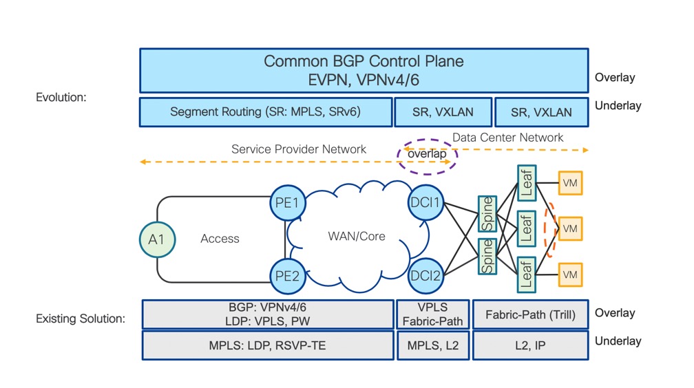
SP Network Overview
Diagram: “Interconnect – High Level” displays how DCI is connected to CO/DC as well as to service provider core. DCI provides L3 Interconnect and therefore does not participate in L2 Bridging. To be able to keep DCI L2 free, Leaves (L1, L2, L3 and L4) have to provide L2 and L3 functionality in the same service instance.
EVPN provides L2 bridging (L2 stretch across multiple computes) which is needed only on Leaves, when L3 routing via EVPN distributed anycast gateway is used. In our example, H1 and H2 are connected to the same L2 domain.
It is very important to realize that DCI has to terminate each service instance (represented by L3 VRF) to provide IP summarization of IP routes advertised from CO to Core.
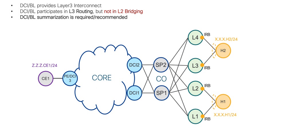
Interconnet – High Level
Before we describe BGP Control Plane signaling, let’s take a look at required L3 forwarding entries on nodes in the diagram: “VRF Entries” in detail. Same as in the diagram: “Interconnect High Level”, we have one customer VRF represented in orange on Leaves (L1, L2, L3 and L4). Hosts H1 and H2 are connected to the same subnet X.X.X.0/24 and this subnet is stretched across all Leaves (L1, L2, L3 and L4). Each Leaf is a Distributed Anycast Gateway for this subnet. Distributed anycast gateway is achieved via Integrated Routing and Bridging Interface (IRB) which is configured in VRF and represents IP default gateway for all hosts in subnet X.X.X.0/24.
Very important VRF FIB entry are host-routes (X.X.X.H1 and X.X.X.H2). This allows optimal inter-subnet routing directly on each Leaf. Z.Z.Z.0/24 is remote subnet originated by PE/DCI3, but subnet Z.Z.Z.0/24 is re-originated by DCI1 and DCI2, therefore, each Leaf’s FIB entry displays DCI1 and DCI2 as next-hop for Z.Z.Z.0/24.
Spines SP1 and SP2 don’t terminate any L2 or L3 service.
DCI1 and DCI2 VRF FIB entry has to contain all host-routes advertised by Leaves in CO. DCI cannot optimally forward traffic to hosts H1 and H2 without host-route FIB entry, because summarized subnet route X.X.X.0/24 is reachable via leaves L1, L2, L3 and L4.
To achieve scalability, DCI cannot advertise all VRF host-routes from CO to remote PEs or DCIs. Remote devices would not be able to install all VRF host-routes into FIB. DCI1 and DCI2 re-advertise only summarized VRF subnet route X.X.X.0/24 to remote PE/DCI3.
PE/DCI3 VRF FIB subnet X.X.X.0/24 is reachable via DCI1 and DCI2. Packet with destination IP address X.X.X.H1 or X.X.X.H2 sent from PE/DCI3 arrives at DCI1 or DCI2. DCI performs VRF IP lookup and because of VRF, host-route entry for each host is able to optimally forward packet with destination IP address X.X.X.H1 to L1 or L2 and packet with destination IP address X.X.X.H2 to L3 or L4.
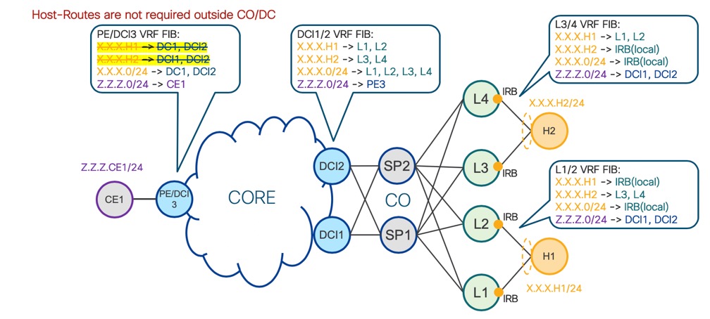
VRF Entries
4. BGP Control Plane Signaling
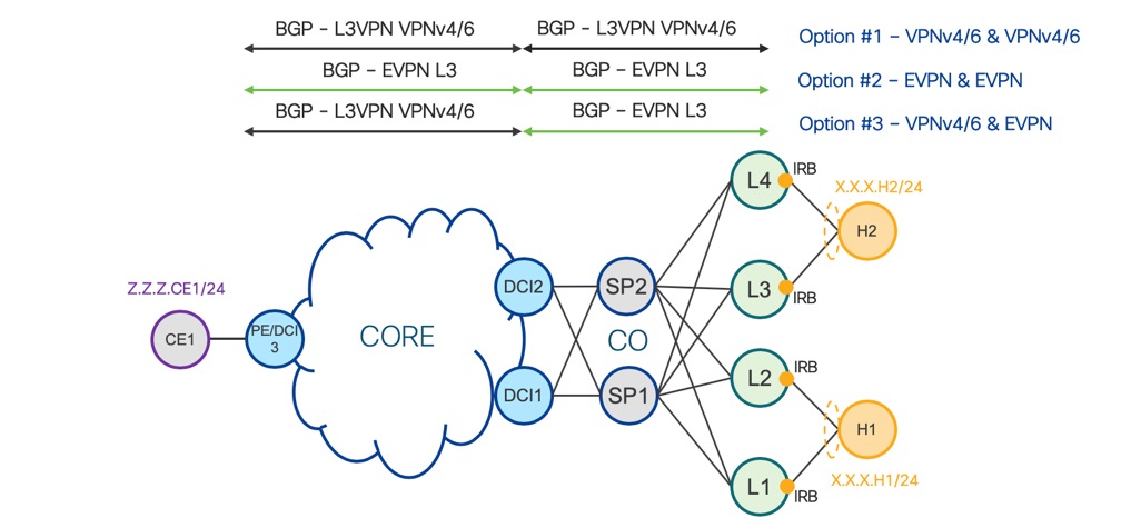
Diagram: “BGP Signaling” displays three different options on how to provide BGP Layer3 Interconnect via different BGP Address-Family (AFI) and the following section of this document summarizes benefits of each of these options.
The key principle is the same for all three options, so advertised routes just have different structures based on the particular address family.
BGP Signaling
4.1. Option #1 – VPNv4/6 & VPNv4/6
Solutions based on VPNv4/6 interconnect is industry proofed to interconnect BGP domains. Diagram “Option #1 – VPNv4/6 & VPNv4/6” displays how DCI1 and DCI2 have to re-advertise VPNv4/6 routes from CO to Core as well as from Core to CO.
DCI has to filter host-routes X.X.X.H1 and X.X.X.H2 to achieve high scale which is described in more detail in the “Forwarding” section of this document.
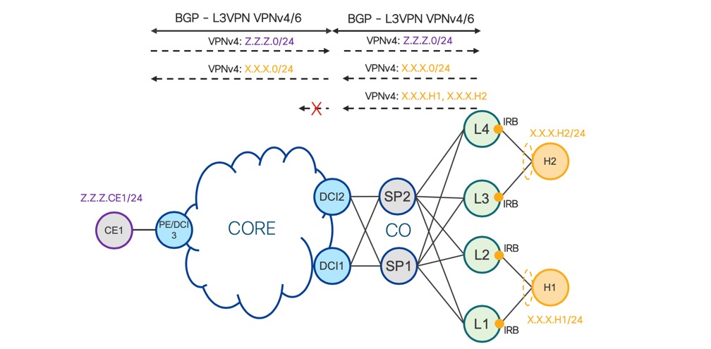
Option #1 – VPNv4/6 & VPNv4/6
Solution based on EVPN Interconnect is solution based on single BGP address family (AFI) end-to-end across the network. Diagram: “Option #2 – EVPN & EVPN” displays how DCI1 and DCI2 have to re-advertise EVPN routes from CO to Core as well as from Core to CO.
EVPN uses route type 2 to advertise host-routes X.X.X.H1 and X.X.X.H2 and route type 5 to advertise subnet X.X.X.0/24 from CO to DCI.
Only EVPN route type 5 is used to advertise subnet Z.Z.Z.0/24 from Core to DCI.
DCI has to filter host-routes X.X.X.H1 and X.X.X.H2 to achieve high scale which is described in further detail in the“Forwarding” section of this document.
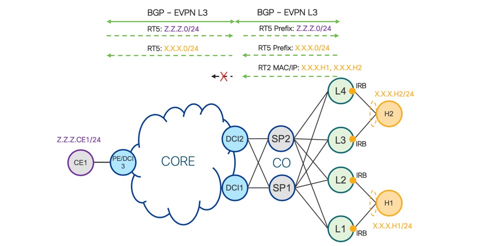
Option #2 – EVPN & EVPN
4.3. Option #3 – VPNv4/6 & EVPN
Solution displayed in diagram: “Option #3 – VPNv4/6 & EVPN” is based on VPNv4/6 and EVPN interconnect. This solution benefits from both previous options and is also a recommended solution. VPNv4/6 stays in Service Provider Core/WAN network as a single BGP address family (AFI), therefore no existing L3VPN service needs to change BGP control plane signaling. EVPN in CO/DC is needed for L2 subnet stretch between Leaves: L1, L2, L3 and L4. When EVPN is used to advertise L3 host-routes X.X.X.H1 and X.X.X.H2 via route type 2 and subnet X.X.X.0/24 via route-type 5, only one single BGP address family is used in CO/DC.
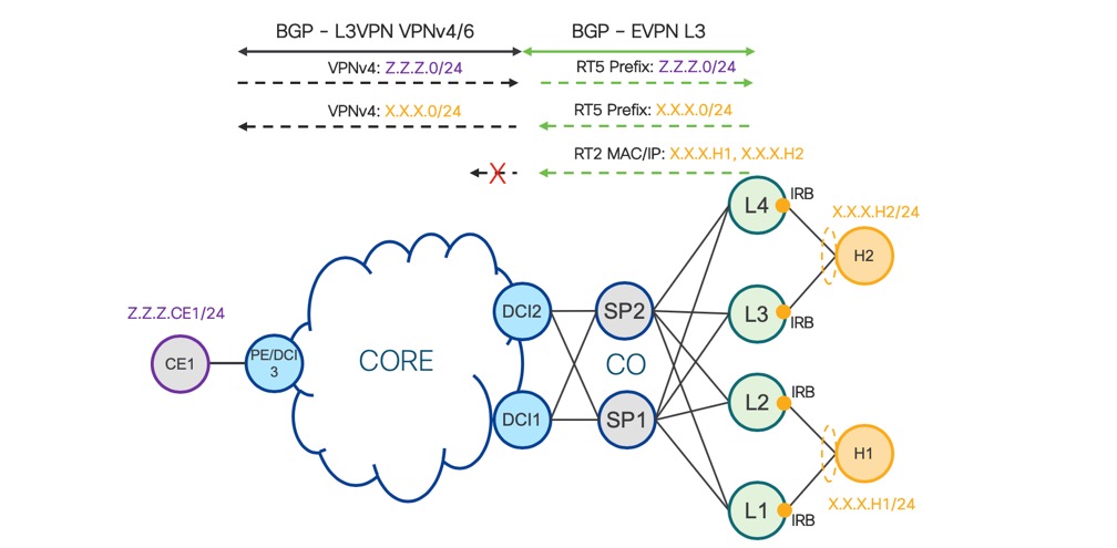
Option #3 – VPNv4/6 & EVPN
Option #1 –
VPNv4/6 & VPNv4/6
+ VPNv4/6 Industry proofed solution
for Layer3 VPN
+ DCI doesn’t need to understand BGP EVPN AF
- Leaf has to peer with Route-Reflector via both BGP EVPN and VPNv4/6 AF
EVPN AF to support L2 stretch (MAC advertisement) across DC/CO between Leaves
EVPN AF to sync ARP/ND for Multi-Homed All-Active
- DC/CO Route-Reflector has to
support both BGP EVPN and VPNv4/6 AF
- Leaf has to advertise VM
Host-Routes via VPNv4/6
Option #2 –
EVPN & EVPN
+ Single BGP Address Family End-To-End in Network
- Existing L3 VPNv4/6 services has
to be migrated to L3 EVPN
No technical benefit to migrate existing L3 VPNv4/6 to L3 EVPN
Option #3 –
VPNv4/6 & EVPN
+ Recommended solution which benefits from both Options #1 and #2
+ New DC/CO - Leaf, Route-Reflector use single BGP AF EVPN
+ Existing L3 VPNv4/6 services stay untouched
This section cover most common data planes: MPLS and VXLAN.
When MPLS data plane is used in Service Provider Core/WAN and CO/DC network, doesn’t matter which BGP address family is used for L3 signaling, because the packet structure is always the same.
Diagram “MPLS - PE to Leaf” displays data path from PE/DCI3 to L1 or L2 via DCI1 or DCI2.
1. PE/DCI3 encapsulates original IP packet with destination IP address X.X.X.H1
a. PE/DCI3 imposes transport MPLS label of DCI1 or DCI2 based on BGP Multipath selection
b. PE/DCI3 imposes service VRF MPLS label signaled via BGP control plane by DCI1 or DCI2
2. Any P router in Core network load balance (per-flow) MPLS traffic based on the inner IP header
3. When DCI1 or DCI2 receives the packet, VRF MPLS label is most top label, because of Penultimate Hop Popping (PHP) operation
4. DCI1 or DCI2 performs VRF FIB lookup based on the inner IP packet destination address (X.X.X.H1)
5. DCI1 or DCI2 encapsulates original IP packet with destination IP address X.X.X.H1
a. DCI1 or DCI2 imposes transport MPLS label of L1 or L2 based on BGP Multipath selection
b. DCI1 or DCI2 imposes service VRF MPLS label signaled via BGP control plane by L1 or L2
6. SP1 or SP2 nodes in CO/DC load balance (per-flow) MPLS traffic based on inner IP header
7. When L1 or L2 receives packet, VRF MPLS label is most top label, because of Penultimate Hop Popping (PHP) operation
8. L1 or L2 performs VRF FIB lookup based on inner IP packet destination address (X.X.X.H1)
9. L1 or L2 forwards via IRB original IP packet to H1
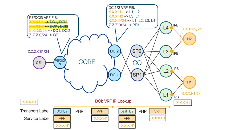
MPLS - PE to Leaf
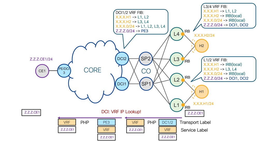
Diagram “MPLS - Leaf to PE” displays data path from L1 or L2 to PE/DCI3 via DCI1 or DCI2. Forwarding principles are the same as described for data path from PE/DCI3 to L1 or L2 via DCI1 or DCI2.
MPLS - Leaf to PE
When VXLAN data plane is used in CO/DC network BGP EVPN address family must be used for L3 signaling.
Diagram “VXLAN - PE to Leaf” displays data path from PE/DCI3 to L1 or L2 via DCI1 or DCI2.
1. PE/DCI3 encapsulates original IP packet with destination IP address X.X.X.H1
a. PE/DCI3 imposes transport MPLS label of DCI1 or DCI2 based on BGP Multipath selection.
b. PE/DCI3 imposes service VRF MPLS label signaled via BGP control plane by DCI1 or DCI2
2. Any P router in Core network load balance (per-flow) MPLS traffic based on the inner IP header
3. When DCI1 or DCI2 receives the packet, VRF MPLS label is the most top label, because of Penultimate Hop Popping (PHP) operation
4. DCI1 or DCI2 performs VRF FIB lookup based on the inner IP packet destination address (X.X.X.H1)
5. DCI1 or DCI2 encapsulates the original IP packet with destination IP address X.X.X.H1
a. DCI1 or DCI2 imposes IP + UDP header of L1 or L2 based on BGP Multipath selection.
b. DCI1 or DCI2 imposes VXLAN header with L3 VNI signaled via BGP EVPN control plane by L1 or L2
c. DCI1 or DCI2 imposes inner ethernet header based on RFC7348
6. SP1 or SP2 nodes in CO/DC load balance (per-flow) IP traffic based on outer IPv4+UDP header or based on outer IPv6 flow label
7. L1 or L2 performs VRF FIB lookup based on inner IP packet destination address (X.X.X.H1)
8. L1 or L2 forwards via IRB original IP packet to H1
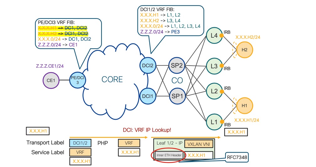
VXLAN – PE to Leaf
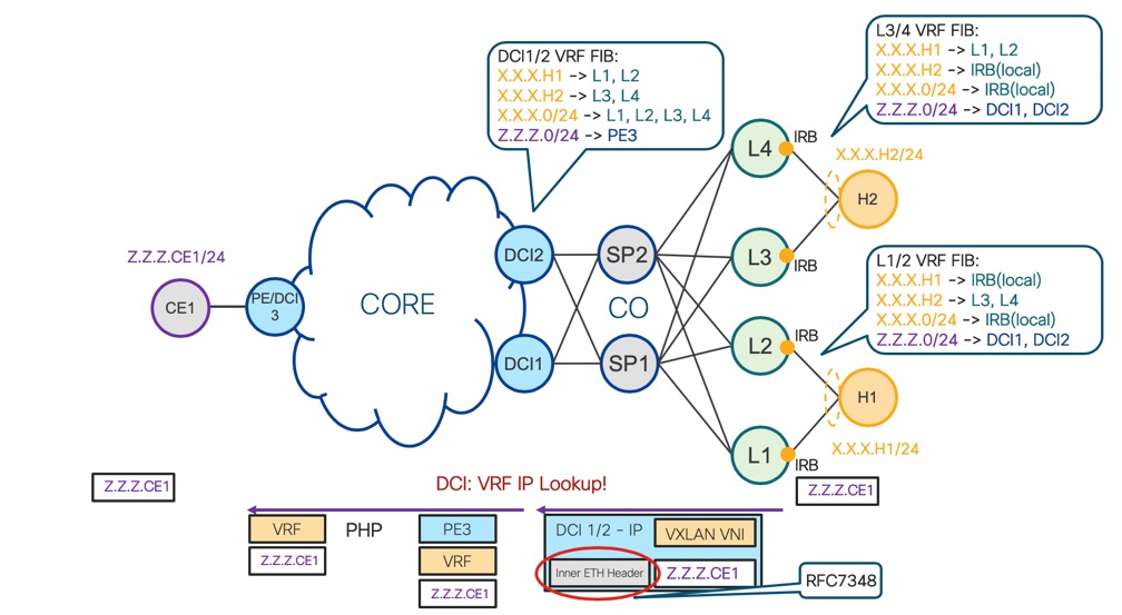
Diagram “VXLAN - Leaf to PE” displays data path from L1 or L2 to PE/DCI3 via DCI1 or DCI2. Forwarding principles are the same as described for data path from PE/DCI3 to L1 or L2 via DCI1 or DCI2.
VXLAN - Leaf to PE
MPLS Data
Plane
+ The packet structure
is always identical, regardless of BGP VPNv4/6 or L3 EVPN Control Plane
+ MPLS
Load-Balancing (ECMP) based on Inner IP Header Lookup

VXLAN Data
Plane
- RFC7348
requires Inner Ethernet encapsulation. It’s unnecessary overhead for L3 Forwarding

6. Implementation & Configuration
Diagram “DCI Route-Target” displays three options of Layer3 interconnect described earlier in this document. This part of document focuses on IOS-XR DCI implementation which is based on two types of Route-Targets (RT). Diagram “DCI Route-Target” displays violet RT which is used to import and export routes from/to Core and orange RT which is used to import and export routes from/to CO/DC. To distinguish in configuration between these two types of RTs keyword “stitching” is used.
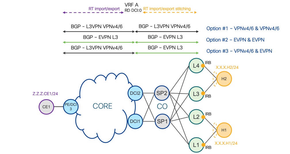
DCI Route-Target
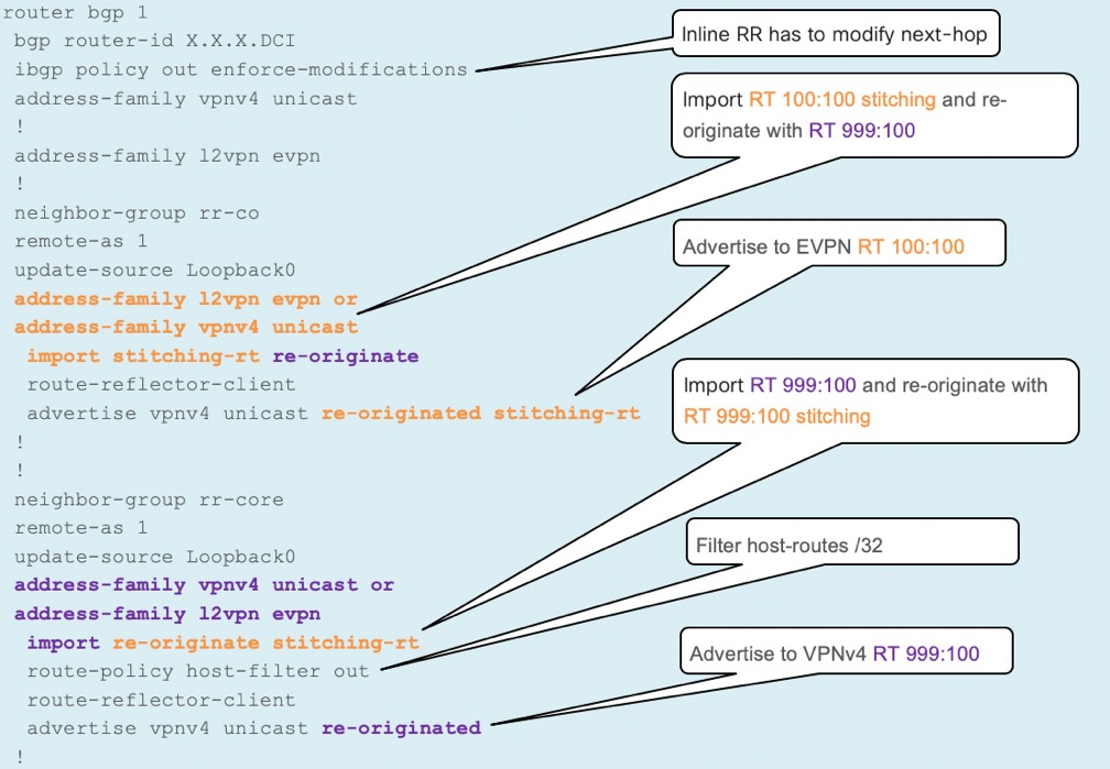
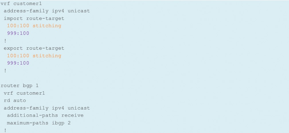
“DCI VRF Configuration” below displays RT configuration together with VRF BGP configuration. This part shows only the configuration for DCI which needs to be done for each VRF/Customer.
DCI VRF Configuration:
“DCI BGP Configuration” below displays initial configuration for L3 Interconnect. Based on options discussed earlier in this document, particular AF is used towards CO/DC and Core/WAN.
DCI BGP Configuration: